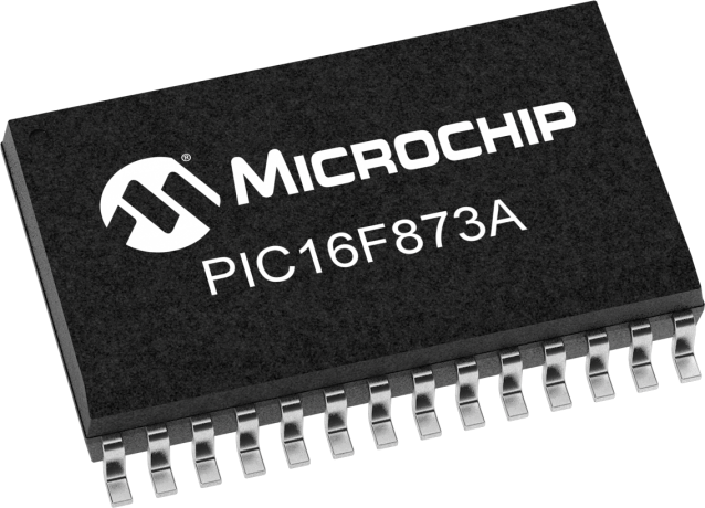
The same code shown in Example can be used. See Table for Reset value for specific condition. For all other cases of low-voltage ICSP, the part may be programmed at the normal oper- ating voltage. However, if flag bit IBOV was previously set, it must be cleared in firmware Shaded cells are not used for synchronous slave reception. This document contains device specific information about the following devices:
| Uploader: | Maudal |
| Date Added: | 15 April 2007 |
| File Size: | 62.3 Mb |
| Operating Systems: | Windows NT/2000/XP/2003/2003/7/8/10 MacOS 10/X |
| Downloads: | 57705 |
| Price: | Free* [*Free Regsitration Required] |
This is because the F baud rate error in some cases In Timer mode, Timer1 increments every instruction cycle. O Comparator 1 output.

These registers are reserved; maintain these registers clear. The same code shown in Example can be used.
Osc Type LP These values are for design datxsheet only. Mode XT HS If 9-bit transmission is selected, the ninth bit should be loaded in bit TX9D. This high speed simulator is designed to debug, analyze and optimize time intensive DSP routines.
This reference will only be as The master controller Processor 1 initiates the data transfer by sending the SCK signal. They are not affected by a WDT pic16f873 which is viewed as the resumption of normal operation After the third address sequence is performed, the UA bit is not set, the module is datahseet configured in Transmit mode and clock stretching is controlled by the BF flag as in 7-bit Slave Transmit mode see Figure With these two timers on-chip, most applications need no external Reset circuitry.
Repeated Start or Stop conditions. The Timer1 oscillator is identical to the LP oscillator. Negative current is defined as current sourced by the pin. SCL see Figure Datashert cells are not used by PWM and Timer2.
However, if flag bit IBOV was previously set, it must be cleared in firmware See Table for Reset value for specific condition. BOR is unknown on Power-on Reset. Interrupt eatasheet generated once the Stop condition is complete.
28/40/44-Pin Enhanced Flash Microcontrollers
In Asynchronous Counter mode, the capture operation may not work. Shaded cells are not used by Timer0. Higher leakage current may be measured at different input voltages.
When code-protected, the device programmer can no longer access data or program memory; this does NOT inhibit internal reads or writes. For all other dafasheet of low-voltage ICSP, the part may be programmed at the normal oper- ating voltage.
Shaded cells are not used by the BRG. Shaded cells are not used by the Watchdog Timer. Not available on pin devices.
blog. Datasheet search blog. Semiconductor news
The leakage current on the MCLR pin is strongly dependent on the applied voltage level. In Counter mode, it increments on every rising edge of the external clock input. When the wake-up is due to an interrupt and the GIE bit is set, the PC is loaded with the interrupt vector h.
This buffer is dataeheet Schmitt Trigger input when used in Serial Programming mode. Refer to Figure for load conditions.

No comments:
Post a Comment